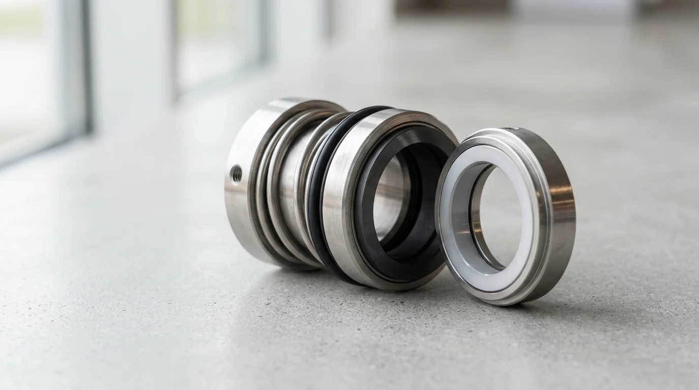
A small drip at the seal chamber can be the first sign of a much larger reliability problem. In rotating equipment, mechanical seal leakage often starts as minor weepage, but it can quickly contaminate bearing oil, damage shafts, increase emissions, and turn a routine repair into an expensive shutdown. Because seals account for a large share of pump failures, maintenance teams need a fast, disciplined way to separate normal lubrication film from abnormal process leakage. This guide explains what to look for, how to classify leak severity, why early detection protects uptime and compliance, and when a planned seal replacement is safer than continued operation.
Why Locate Mechanical Seal Leakage Early
Mechanical seals are the primary containment barrier in centrifugal pumps, compressors, and agitators. Despite their precision engineering, they remain the most vulnerable component in rotating equipment, accounting for an estimated 60 to 70 percent of all pump failures in process industries. Quickly identifying the exact source and severity of mechanical seal leakage prevents localized seal degradation from cascading into catastrophic equipment failure, thereby safeguarding operational continuity and maintaining regulatory compliance.
How Early Detection Reduces Downtime
When a mechanical seal begins to fail, the initial symptom is typically a micro-leak, often measured in just 5 to 10 drops per minute above the established baseline. If ignored, the fluid can breach the bearing housing isolators. Contamination of bearing lubricating oil by process fluid can significantly reduce bearing life—in some studies, trace water contamination (e.g., 20 ppm) has been shown to cut bearing life by nearly half.
By identifying the seal leak at the micro-leak stage, maintenance teams can schedule a targeted seal replacement, which typically requires four to six hours of planned downtime. In contrast, allowing the leak to progress until the bearings fail often results in severe shaft deflection, impeller-to-casing contact, and motor overload. This secondary damage multiplies downtime, turning a routine seal change into a comprehensive pump overhaul.
Commercial Risks of Uncontrolled Leakage
Uncontrolled mechanical seal leakage introduces severe commercial and regulatory liabilities. For petrochemical and refining operations, the release of volatile organic compounds (VOCs) is strictly governed by environmental regulations such as the EPA’s Leak Detection and Repair (LDAR) program. Under these frameworks, a seal emitting VOCs above 500 parts per million (ppm) often triggers mandatory reporting and strict repair timelines, while emissions exceeding 10,000 ppm can result in substantial fines and mandated unit shutdowns.
Beyond regulatory penalties, escaping process fluid represents a direct loss of valuable inventory. High-value refined products, specialized heat transfer fluids, or concentrated chemical catalysts escaping at a rate of just 3 milliliters per minute will result in the loss of over 400 gallons annually per pump. Furthermore, leaking process fluids often cause external corrosion on pump bases and structural steel, necessitating expensive metallurgical remediation.
How to Define and Classify Mechanical Seal Leakage
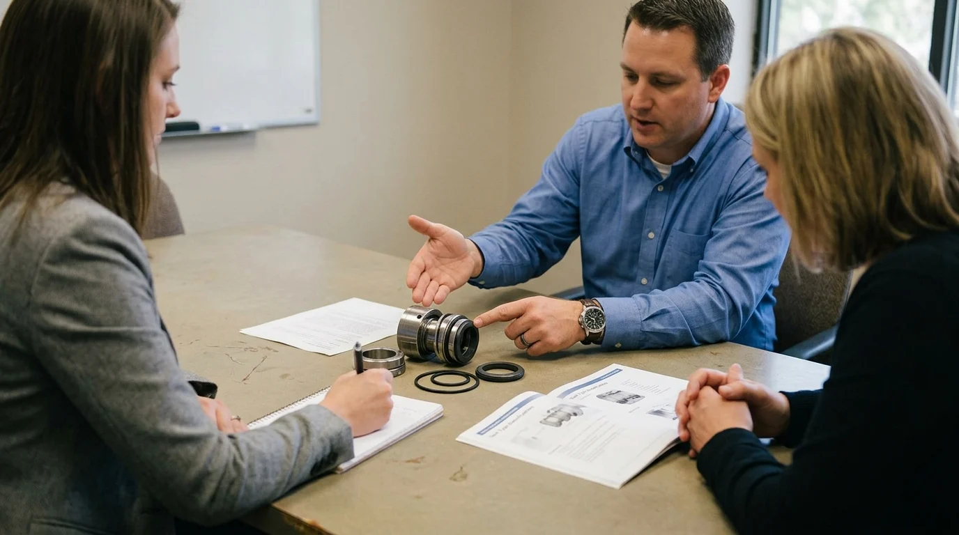
To accurately diagnose mechanical seal health, you must first define what constitutes abnormal leakage. By design, all contacting mechanical seals leak. A microscopic fluid film, typically ranging between 0.25 and 1.0 microns thick depending on the application, must exist between the rotating and stationary faces to provide essential lubrication and cooling. The diagnostic challenge lies in distinguishing between necessary design weepage and pathological process leakage.
Normal Weepage vs Process Leakage
Normal weepage is the functional byproduct of the lubricating fluid film vaporizing or migrating across the seal faces. For a typical water-based application on a 2-inch (50 mm) shaft operating at 3,600 RPM, acceptable weepage is generally 1 to 2 drops per minute. In many hydrocarbon applications running at elevated temperatures, this weepage vaporizes instantly upon hitting atmospheric pressure, rendering it entirely invisible to the naked eye.
Conversely, process leakage is characterized by a volumetric flow that exceeds the vaporization capacity of the seal faces, resulting in visible liquid accumulation. When leakage rates surpass 60 drops per minute (approximately 3 to 4 milliliters per minute), the seal has lost its dynamic stability. This transition from vaporous weepage to continuous liquid dripping indicates a breakdown in face flatness, severe thermal distortion, or a hydraulic opening force that has overcome the mechanical spring and fluid closing forces.
Leakage Patterns from Face Wear or Elastomer Damage
The physical characteristics and timing of the leakage provide critical forensic clues regarding the failing internal component. Leakage originating from primary face wear typically presents as a steady, progressive increase in volume over weeks or months. As the carbon, silicon carbide, or tungsten carbide faces experience abrasive wear, the fluid film thickens, allowing more product to escape. This type of leakage is usually consistent and proportional to the pump’s discharge pressure while the equipment is running.
In contrast, leakage caused by secondary elastomer damage—such as O-ring extrusion, chemical swelling, or compression set—often manifests as sudden, erratic, or static leakage. If an O-ring has hardened due to thermal degradation, it loses its elasticity and its ability to track the microscopic axial movements of the seal face. This results in heavy liquid leakage when the pump is shut down and the dynamic fluid pressure drops, a phenomenon known as static leakage.
Ranking Severity by Fluid Hazard
The urgency of addressing a seal leak is dictated by the volume of escaping fluid and its specific hazard classification. Rank leakage severity by cross-referencing the volumetric rate against the fluid’s toxicity, flammability, and environmental impact. API 682 guidelines provide a robust framework for this categorization.
| Hazard Category | Fluid Characteristics | Acceptable Visible Leakage | Action Threshold |
|---|---|---|---|
| Category 1 | Benign (Water, mild aqueous) | < 5 drops/min | > 60 drops/min (Schedule repair) |
| Category 2 | Flammable / Combustible | Zero visible liquid | > 500 ppm VOC (LDAR compliance) |
| Category 3 | Toxic / Lethal (H2S, HF acid) | Zero visible / Zero vapor | > 10 ppm atmospheric (Immediate shutdown) |
| Category 4 | High-Temperature (> 176°C) | Light steam / vapor | Visible liquid pooling (Safety hazard) |
This hierarchy dictates response protocols. A 10-drop-per-minute leak on a cooling water pump might be documented and monitored for months, whereas a localized vapor detection of 50 ppm on a hydrofluoric acid alkylation pump demands instantaneous unit isolation.
Fastest Methods to Detect Mechanical Seal Leakage
Rapid detection of mechanical seal leakage is paramount for preventing collateral equipment damage. Modern industrial facilities employ a tiered approach to leak detection, combining traditional operator rounds with advanced condition monitoring systems to identify the loss of containment at the earliest possible stage.
Visual Inspection, Drain Monitoring, and Seal Pot Checks
Visual inspection remains the most fundamental detection method. Look for pooling fluid under the pump casing, staining on the baseplate, or localized vapor clouds around the gland. Because visual checks are inherently lagging indicators, facilities should also rely on drain monitoring and specialized seal pot checks.
For dual unpressurized seals utilizing an API Plan 52 arrangement, the seal pot captures inboard seal leakage. A rapid increase in the seal pot liquid level or an unexpected rise in reservoir pressure indicates a primary inboard face failure. For dual pressurized seals utilizing an API Plan 53A system, a drop in barrier fluid pressure of more than 0.5 bar over a 24-hour period, or a requirement to refill the reservoir more frequently than every 28 days, provides definitive evidence of a seal leak before any process fluid reaches the atmosphere.
Using Vibration, Temperature, and Pressure Trends
Advanced condition monitoring leverages instrumentation to detect the physical symptoms of a failing seal before volumetric leakage occurs. High-frequency vibration analysis, particularly Acoustic Emission (AE) monitoring in the 20 kHz to 100 kHz range, can detect the microscopic friction caused by a collapsing fluid film. However, AE monitoring requires establishing a precise, clean baseline to be effective and avoid false positives.
Similarly, temperature trends offer critical diagnostic insights. Thermocouples embedded directly in the stationary seal gland or monitoring the flush line return can detect thermal anomalies. A sudden temperature spike of 10°C to 15°C above the established baseline often indicates excessive frictional heat, a direct precursor to face blistering and heavy leakage. Note that thermocouple readings can vary significantly based on the flush plan and ambient conditions, so they must be interpreted in context. Monitoring the differential pressure between the stuffing box and the barrier fluid also highlights hydraulic instabilities.
Comparing Detection Speed and Reliability
Selecting the appropriate detection method requires balancing the required speed of detection against installation costs and system reliability. High-hazard applications justify continuous electronic monitoring, while balance-of-plant utility equipment may rely on daily manual inspections.
| Detection Method | Primary Indicator | Detection Speed | Reliability / False Positives | Implementation Cost |
|---|---|---|---|---|
| Acoustic Emission | High-frequency friction | Instantaneous (Predictive) | High (Requires expert analysis) | High (Varies by system) |
| Seal Pot Level/Pressure | Volumetric fluid change | Fast (Hours to Days) | Very High (Direct measurement) | Medium (Included in API Plans) |
| Embedded Thermocouple | Face temperature spike | Fast (Minutes to Hours) | Medium (Influenced by process) | Medium ($500 – $1,000) |
| Visual / Drain Check | Fluid pooling / staining | Slow (Days to Weeks) | Low (Subject to operator diligence) | Low (Labor cost only) |
By integrating these diverse methodologies into a centralized distributed control system (DCS), you can set automated, multi-variable alarms that trigger maintenance alerts long before a catastrophic seal blowout occurs.
Step-by-Step Process to Locate Mechanical Seal Leakage
Once a mechanical seal leak is suspected, execute a systematic diagnostic process. Randomly dismantling the equipment destroys critical forensic evidence. A structured localization process ensures that the exact leak path is identified, allowing for accurate repair planning.
Isolating the Leakage Source
First, isolate the true source of the fluid. Fluid pooling under a pump does not guarantee a mechanical seal failure. Rule out auxiliary systems, such as leaking flange gaskets on the suction or discharge piping, degraded threaded connections on the seal flush lines, or simple atmospheric condensation from cold-service applications.
Clean and thoroughly dry the entire pump casing, gland, and baseplate. For low-pressure gas seals or light hydrocarbon applications where the leak is invisible, apply a specialized liquid leak detector (soapy water solution) to the gland connections or utilize an ultrasonic leak detector to pinpoint the exact emission source. If the fluid or acoustic signature is confirmed to be emanating strictly from the seal gland area, proceed to component-level isolation.
Inspection Sequence Around the Gland
Inspecting the gland area requires a logical sequence, moving systematically from static exterior connections to the dynamic internal components. Follow these steps to eliminate potential leak paths:
- Inspect static connections: Check all NPT or flanged connections on the gland plate, including the flush, quench, and drain ports. A loose fitting or degraded thread sealant here is easily remedied without requiring pump disassembly.
- Examine the gland plate interface: Look at the interface between the gland plate and the pump stuffing box face. Leakage here indicates a failure of the static gland gasket, often caused by improper torqueing sequences, uneven bolt tension, or chemical attack.
- Observe dynamic clearances: Check the interface between the pump shaft (or shaft sleeve) and the inner diameter of the gland. If liquid is actively spraying or dripping from this dynamic clearance while the shaft is rotating, the primary seal faces or the dynamic secondary O-ring have been compromised.
- Check for static leakage: Observe the equipment when the shaft is completely stationary. Heavy static leaks strongly point to elastomer compression set or severe mechanical face distortion.
Documenting Findings for Root Cause Analysis
Thorough documentation of the localized leak is critical for subsequent Root Cause Failure Analysis (RCFA). Record the exact leakage rate. While utilizing a graduated cylinder and stopwatch provides precise volumetric data (milliliters per minute), this method is often impractical or unsafe for high-temperature or volatile fluids. In such cases, rely on visual estimation or closed-system level changes rather than risking personnel exposure.
Log the operating parameters at the exact time of the leak—such as stuffing box pressure, process temperature, and specific vibration velocity—into the computerized maintenance management system (CMMS). Attach photographs of the leak path, localized corrosion, or crystallized product build-up to the work order. This granular data allows you to accurately update Mean Time Between Repairs (MTBR) metrics and determine if the failure requires an upgraded seal design.
How to Decide Between Adjustment, Repair, and Replacement
Discovering a mechanical seal leak does not automatically dictate an immediate pump overhaul. Evaluate the severity of the leak against operational safety and production demands to determine whether the leakage can be mitigated through operational adjustments, safely managed until a planned turnaround, or requires an emergency shutdown.
When Operating Changes Can Correct Leakage
In certain scenarios, mechanical seal leakage is merely a symptom of transient process conditions. If the leak is caused by the process fluid flashing (vaporizing) across the seal faces due to inadequate vapor pressure margins, targeted operational changes can stabilize the seal.
Increasing the stuffing box pressure by slightly throttling the pump discharge valve, or lowering the fluid temperature by increasing the flow of an API Plan 11 or Plan 21 flush, can restore the necessary liquid film. For dual pressurized seals, if the barrier fluid pressure has dropped below the recommended differential above the stuffing box pressure, the inboard faces may separate. Re-pressurizing the barrier system to the correct specification can often re-seat the faces and halt the leakage, entirely avoiding a mechanical tear-down.
When Leakage Requires a Planned Shutdown
When operational adjustments fail to correct the leakage, but the volume remains within safe limits, the repair can often be deferred to a planned shutdown. This strategy requires establishing strict, quantifiable monitoring thresholds.
For example, if a boiler feed water pump exhibits a steady, minor leak and vibration signatures remain stable, the equipment can likely operate safely for several weeks. During this period, procure the necessary replacement cartridge seal and schedule the required labor. Deferring the repair prevents the disruption of continuous production processes and avoids premium emergency maintenance costs. However, this mandates daily monitoring to ensure the leak rate does not exponentially accelerate.
Balancing Safety, Cost, and Reliability
The ultimate decision to adjust, repair, or replace hinges on balancing personnel safety, Total Cost of Ownership (TCO), and long-term equipment reliability. If a leak involves hazardous or highly flammable chemicals, safety supersedes all commercial considerations; an emission exceeding regulatory thresholds or a visible drip of a corrosive acid demands immediate unit isolation and replacement.
From a cost perspective, attempting to repair a heavily degraded legacy component seal with a history of chronic failures is rarely economical. Weigh the cost of a new, application-specific cartridge replacement against the exponentially higher penalty of repeated downtime, lost production, and potential collateral damage to the pump shaft and bearings. By rigorously applying failure data and fluid hazard analysis, you can optimize your mechanical seal lifecycle strategies and manage leaks effectively.
Key Takeaways
- Treat a leakage increase of 5 to 10 drops per minute above the normal baseline as an early warning that requires inspection.
- Distinguish normal seal weepage from process leakage before shutdown decisions, because contacting seal faces need a microscopic lubricating film to operate safely.
- Inspect the seal area quickly when leakage appears to prevent process fluid from contaminating bearing oil and shortening bearing life.
- Schedule seal replacement during planned downtime when leakage is still minor, since a controlled repair may take four to six hours compared with a much longer pump overhaul.
- Escalate VOC-related seal leakage immediately because emissions above regulatory thresholds can trigger mandatory reporting, repair deadlines, fines, or shutdowns.
- Document leak rate, fluid type, operating conditions, and visual evidence so maintenance teams can identify whether the seal, gland, piping, or bearing housing is the true source.
Frequently Asked QuestionsHow much mechanical seal leakage is considered normal?
A small amount of weepage is normal because seal faces need a lubricating fluid film. In many water-based pump applications, 1 to 2 drops per minute may be acceptable, while a rise of 5 to 10 drops per minute above baseline should be investigated.
What is the fastest way to locate mechanical seal leakage?
Start by confirming the leak source at the seal chamber, then check leakage rate, spray pattern, process fluid traces, bearing housing contamination, and nearby piping or gasket joints. Compare findings against the pump’s normal baseline before deciding on repair.
Why should mechanical seal leaks be fixed early?
Early action prevents process fluid from reaching bearings, couplings, motor components, and pump foundations. A planned seal replacement may take only four to six hours, while ignored leakage can lead to bearing failure, shaft damage, and a full pump overhaul.
Can all mechanical seals leak by design?
Yes. Contacting mechanical seals require a microscopic film between the rotating and stationary faces for lubrication and cooling. The goal is not zero leakage in every case, but recognizing when normal weepage becomes abnormal process leakage.
What are common signs of mechanical seal failure?
Common signs include rising drip rate, visible spray, crystallized product around the gland, unusual odor, vapor emissions, bearing oil contamination, vibration increase, overheating, or corrosion around the pump base.
Media Contact
Company Name: Ningbo Victor Seals Co., Ltd.
Email: Send Email
Country: China
Website: https://www.victor-seals.com/